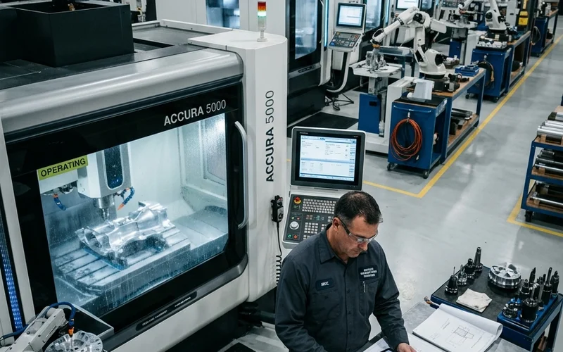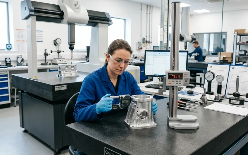
In precision manufacturing, an ancient shop-floor proverb holds absolute truth: “You cannot machine what you cannot measure.”
Whether fabricating titanium aerospace turbine housings, automotive fuel-injection nozzles, or orthopedic bone plates, engineering tolerances are routinely specified in microns (0.001mm / 0.00004”). In these high-stakes industries, Quality Control (QC) is not a disconnected department at the end of the factory—it is an active, continuous discipline executed directly at the machine tool.
The Core Metrology Toolkit Every CNC Machinist Must Master
1. Digital and Outside Micrometers (0.001mm Resolution)
The outside micrometer is the gold standard for measuring external diameters, shaft journals, and thickness:
- Ratchet Stop Usage: Always turn the thimble using the ratchet or friction thimble (2 to 3 clicks) to apply consistent measuring force without flexing the C-frame.
- Thermal Isolation: Never hold the steel frame of a micrometer in your bare palm for extended periods; body heat will expand the frame, throwing off calibration by several microns. Always use the insulated thermal pad.
- Calibration Verification: Check zero against certified Grade 0 slip gauge blocks before every inspection shift.
2. Internal Three-Point Bore Micrometers & Telescoping Gauges
Standard vernier caliper jaws have flat contact surfaces that cannot accurately measure deep cylindrical bores due to chordal error. Machinists use three-point internal bore micrometers or dial bore indicators calibrated with setting rings to detect bore taper, bell-mouthing, and out-of-roundness.
3. Dial Test Indicators (DTI) & Lever Probes
Featuring graduations down to 0.002mm (0.0001”), DTIs are used to:
- Sweep vise jaws and fixture plates parallel to the X/Y machine axes.
- Indicate cylindrical stock or lathe chucks to runout limits below 0.005mm.
- Tram VMC spindle heads perpendicular to the machine table.
4. Surface Finish Profilometers (Ra & Rz Measurement)
Visual inspection cannot quantify surface roughness. Digital stylus profilometers measure the microscopic peaks and valleys left by cutting tool inserts:
- Ra (Roughness Average): Standard for milling and turning finishes (e.g., Ra 0.8 µm for hydraulic seals, Ra 1.6 µm for general precision faces).
- Correlation with Feeds & Tool Nose Radius: A larger tool nose radius ($R_{\epsilon}$) and lower feed rate ($f$) directly improve surface finish according to the theoretical peak-to-valley formula: $R_{th} = \frac{f^2}{8 R_{\epsilon}}$.
The Impact of Thermal Expansion on Part Dimensions
Metals expand and contract significantly with temperature variations:
- Aluminum alloys have a high Coefficient of Thermal Expansion ($CTE \approx 23 \times 10^{-6}/\text{K}$), meaning a 100mm aluminum part heated by 10°C during heavy machining will expand by 0.023mm (23 microns)—easily exceeding a ±0.01mm drawing tolerance.
- Elite machinists always allow parts to cool to the international reference temperature of 20°C (68°F) with coolant wash before taking final critical inspection readings.
First Article Inspection (FAI) & AS9102 Quality Protocols
In regulated aerospace, defense, and medical sectors, before a machine is authorized to run a continuous production batch, the first machined piece undergoes rigorous First Article Inspection (FAI):
- Every dimension on the engineering blueprint is numbered with a balloon callout.
- The corresponding actual measured dimension, instrument serial number, and tolerance pass/fail verdict are recorded on standardized AS9102 inspection forms.
- If any dimension fails, the machinist must adjust the tool wear offset or correct workholding deflection before signing off on batch production.
At LENOCAM Academy in Manjeri, Kerala, every CNC student learns to inspect, measure, and document their own machined components using calibrated digital metrology instruments and ASME Y14.5 GD&T standards in our dedicated Quality Control laboratory.
Practical CNC training, technical insights, and precision manufacturing knowledge from LENOCAM Academy in Manjeri, Kerala.